MPLS静态LSP配置案例
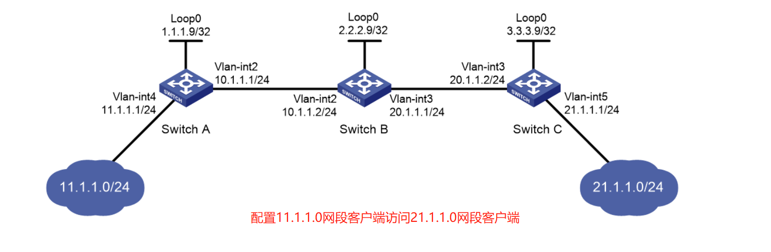
1.组网需求:在Switch A和Switch C之间建立静态LSP,使11.1.1.0/24和21.1.1.0/24这两个网段中互访的报文能够通过MPLS进行传输
2.配置过程:
2.1 配置两边直接路由的路由转发配置:
[SwitchA] ip route-static 21.1.1.0 24 10.1.1.2
[SwitchC] ip route-static 11.1.1.0 255.255.255.0 20.1.1.1
2.2 各LSR开启MPLS,id为loopback地址
A的:
[SwitchA] mpls lsr-id 1.1.1.9
[SwitchA] interface vlan-interface 2
[SwitchA-Vlan-interface2] mpls enable
[SwitchA-Vlan-interface2] quit
B的:
[SwitchB] mpls lsr-id 2.2.2.9
[SwitchB] interface vlan-interface 2
[SwitchB-Vlan-interface2] mpls enable
[SwitchB-Vlan-interface2] quit
[SwitchB] interface vlan-interface 3
[SwitchB-Vlan-interface3] mpls enable
[SwitchB-Vlan-interface3] quit
C的:
[SwitchC] mpls lsr-id 3.3.3.9
[SwitchC] interface vlan-interface 3
[SwitchC-Vlan-interface3] mpls enable
[SwitchC-Vlan-interface3] quit
从 A -> C 方向的:
# 配置Ingress Switch A 【 入口端,配置为ingress 】
[SwitchA] static-lsp ingress AtoC destination 21.1.1.0 24 nexthop 10.1.1.2 out-label 30
# 配置Transit Switch B
[SwitchB] static-lsp transit AtoC in-label 30 nexthop 20.1.1.2 out-label 50
# 配置Egress Switch C 【 出口端配置egress,标明入标签即可 】
[SwitchC] static-lsp egress AtoC in-label 50
从 C -> A 方向的:
# 配置Ingress Switch C 【入口端,配置为ingress】
[SwitchC] static-lsp ingress CtoA destination 11.1.1.0 24 nexthop 20.1.1.1 out-label 40
# 配置Transit Switch B 【 中间LSR,配置类型为transit 】
[SwitchB] static-lsp transit CtoA in-label 40 nexthop 10.1.1.1 out-label 70
# 配置Egress Switch A 【 出口端配置egress,标明入标签即可 】
[SwitchA] static-lsp egress CtoA in-label 70
然后就是两个客户端间的测试,基本上可以通,不通要继续调试