RSTP与MSTP实验
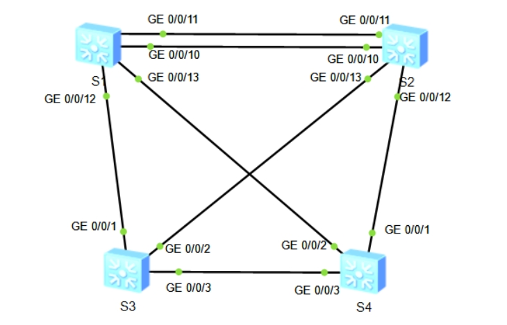
1.实验拓扑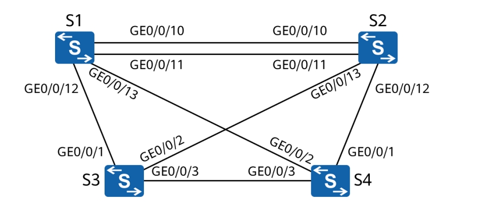
2.实验目标
实现手动修改桥优先级影响根桥选举
实现手动修改端口开销值控制根端口选举
实现手动修改端口优先级控制根端口选举
实现配置 MSTP 以达到不同 VLAN 间流量负载均衡
3.关键技术
3.0 配置RSTP
[S1]stp enable
[S1]stp mode rstp
检查:
dis stp instance 0 brief
dis stp brief
dis stp interface g0/0/2
3.1 实现手动修改桥优先级影响根桥选举
#手动调整 STP 优先级,指定 S1 为主根桥、S2 为备份根桥
[S1]stp priority 4096
[S2]stp priority 8192
3.2 实现手动修改端口开销值控制根端口选举
#修改 S4 的 GEO/0/2 接口的 STP cost 值为 40001
[S4] interface GigabitEthernet 0/0/2
[S4-GigabitEthernet0/0/2] stp cost 40001
3.3 实现手动修改端口优先级控制根端口选举
#在 S1 上修改 GEO/0/11的 STP 接口优先级,使其发送的 BPDU 优于 GEO/0/10 发送的 BPDU
[S1] interface GigabitEthernet 0/0/11
[S1-GigabitEthernet0/0/11] stp port priority 64
STP 接口优先级为 128,数值越小越优。
3.4 实现配置 MSTP 以达到不同 VLAN 间流量负载均衡
MSTP基础配置
在所有交换机上创建 VLAN10、20、30、40、50、60、70、80,配置MSTP 域hcip,并创建两个新的实例 :
Instance 1、Instance 2,将 VLAN10、30、50、70 映射到Instance 1,将VLAN20、40、60、80 映射到
Instance 2,同时将 SW1规划为 MSTI 的主根桥、MSTI2 的备份根桥,
将 SW2 规划为 MSTI2 的主根桥、MSTI1 的备份根桥。
【S1举例,S2、S3、S4一样的配置】
#创建 VLAN
[S1]vlan batch 10 20 30 40 50 60 70 80
#修改 STP 模式为 MSTP
[S1]stp mode mstp
#配置MSTP
[Sl]stp region-configuration
[S1-mst-region] region-name hcip
[S1-mst-region] revision-level 1
[S1-mst-region] instance 1 vlan 10 30 50 70
[S1-mst-region] instance 2 vlan 20 40 60 80
[S1-mst-region] active region-configuration
[S1-mst-region] quit
#配置 SW1 为 MSTI1 的根桥、MSTI2 的备份根桥
[S1] stp instance 1 root primary
[S1] stp instance 2 root secondary
#配置 SW2 为 MSTI2 的根桥、MSTI1 的备份根桥
[S2] stp instance 1 root secondary
[S2] stp instance 2 root primary
检查:
display stp region-configuration
display stp instance 1 brief
3.5 在 S1、S2 上开启 LLDP,查看接口的互联关系 [S1] lldp enable [S2] lldp enable [S2] display lldp neighbor brief